Saturday, October 29, 2011

Designing the Rear firebox mount

     The rear firebox mount appears as an curved sheet that attaches to a support that mounts to the side frames and connects to the bottom of the firebox.  The ash pan attaches to brackets on the front and rear of the mount.  An ash pan section is shown at the rear below the cab floor, probably used by the crew during clean out near the firebox door to catch clinkers and hot ash scrapped out the door.
    The ash pan will be a separate structure bonded in place on the brackets attached to the rear (and front) firebox mounts.
     The view at left shows the general shape of the rear firebox mount sheet showing bolt details for the attachments to the firebox bracket and the mount brackets on both sides of the side frame.   Ash pan brackets are not shown in this view.  They will be located based on the side view above.  The ash pan will be a separate piece that will likely be bonded in place between the front and rear firebox mounts and will have sections at the front of the front firebox mount and rear of the rear firebox mount to complete the pan structure.
    The rear firebox mount attaches to a cross frame structure that in turn is attached to the side frames.  The side view above indicates that the firebox mount is attached to a frame structure between and outside of the side frames.  The mount support structure is close to the rear truck spring mount and may wind up with cross connections to stiffen the outboard edges of the portions outside the side frames. Photos of various locomotives will be analyzed to determine it they may be a composite structure.
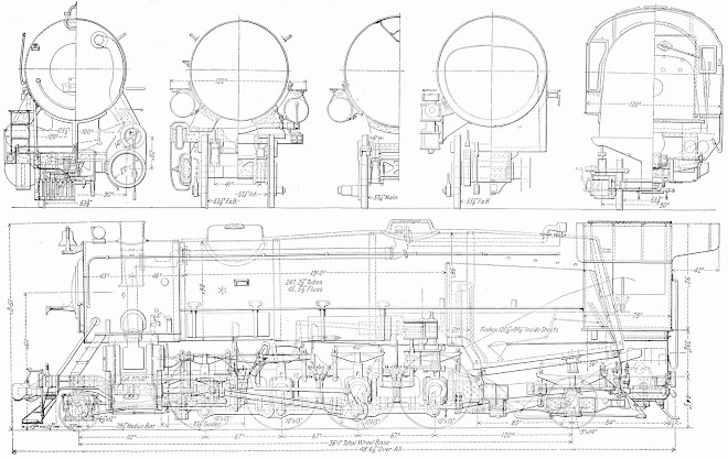
    The support structure for the rear firebox mount is assumed to be about where shown in highlight on the drawing extract at left based on the end view.  The support has one rib at the top and may have another at the bottom to provide rigidity fore and aft as shown in the end view extract previously shown.  The section views on the drawing do not provide clear separation of details.  It would be helpful if a top or bottom view were available, however, the USRA plan obtained from the internet does not include those views.

    The 3D CAD design was started by designing the support frame that will be located between and outside of the side frames.  Flanges were added to provide stiffness as is suggested in the drawings.  The rear firebox support sheet will be attached to the rear of this portion and bolt details added.  The firebox support sheet is bent twice at small angles as it rises above the support.  The final angle is 9 degrees and the first portion is assumed to be about half that based on the side views.  This will give and end view that closely approximates the drawing.

    The lower third of the rear firebox sheet is shown attached to the support brace in the 3D CAD model at left.  This portion is vertical mounted on the brace. The next third will be tilted at a 4.5 degree angle and the top third will be tilted at 9 degrees putting the joint with the firebox at a right angle.


    The CAD illustration at left shows the completed rear firebox support less bolt details.  The vertical sheet is composed of three portions, the lower is at 90 degrees to the support frame, the second is tilted at 4.5 degrees from that and the top is tilted at 9 degrees from vertical as shown in the plans.  The plans show top bracket attachments to the firebox rear and another set of brackets to attach the ash collection funnel box that rides below the firebox and drops down between the side frames.  The ash funnel will be a separate part.
    After the main support sheet is designed, support brackets are attached that will support the firebox at the top and ash funnel at mid point.  The ash funnel brackets are angle iron sections as are the top firebox supports.  The top bracket is angled over the top and does not protrude out the rear.  The next step will be to add bolt details.


    The next illustration shows the rear firebox mount with bolt detailing.  This completes the design of the part.  The next step is to integrate it unto the previously designed rear frame assembly.


   The rear firebox support is shown mounted on the rear frame assembly at left.  Other major detail component parts include the truck spring mounts and truck equalizer bar mounts.  The truck spring mounts are just forward of the rear firebox mount while the equalizer bar mounts are just aft of the forward firebox mount.

Thursday, October 27, 2011

Addition of cab support end sills

    Continued work building up the full design of the back chassis section, one of three sections that make up the entire chassis.  It was necessary to subdivide the overall chassis structure into three sub-assemblies in order to be able to build the chassis in the 3D printer.  Each sub-assembly needed to be no longer that about 10".
    The back section contains two side frames, a front spacer, rear spacer and several detail sections.  For this blog posting the side rails, front spacer, rear spacer and now the cantilevered sill sections that support the cab rear and a number details are finished, design-wise.  Each component has been consuming about 4-6 hours of effort to complete the 3D design model which can then be integrated into the overall back section assembly.
     The rear sill sections are cantilevered out from the side rails.  The locomotive erection and section drawing is shown at left with the rear sill portion highlighted.
    At left is the end view of the sill, below is the side view.  After much evaluation and examination of other material, the side and end views provide a general idea of how the sill is constructed in the plan.
    The sill has the function of supporting the rear panel of the cab and a number of pipes and other details associated with steam locomotives such as water injectors, etc.
    The rear view of the locomotive section shows the main cantilever section shown highlighted.  At the end is a small box that extends the overall sill out to the edge of the cab rear and provides mounting for some details.
    For this design effort only the sill structure is developed, details will be developed and added on later.


    The drawing at left shows the 3D CAD model of both the right and left sill structures.  They are mirror images of one another.  They are composed of individual plates in a manner very similar to the prototype locomotive.  Bolt detail was added where shown on the plan.


   The 3D CAD model at left illustrates the end sills on each side of the side rails outboard of the rear spacer.  A number of smaller details remain to be added later.
   

Monday, October 24, 2011

Back Frame Rear Spacer

    The rear spacer shown at left includes the drawbar pin mounting features and the drawbar tensioner pad.  In the prototype locomotive the tensioner pad butts tightly up against a mating pad on the tender and tensioning wedges are inserted to put the drawbar in tension removing any slop that might otherwise occur.  The drawbar is located in a slot just below the tensioner pad.  
    One of the drawbar pin mounting holes is visible at the left on the illustration.  The illustration is a jpeg output from the Alibre Design program and is scaled at 1/2"=1'.  
    The front and rear spacers are shown in position on the back frame assembly, one of three that make up the bulk of the chassis frame.  Bolt detail was added to the sides of the back frame where they will appear on the prototype.  Subsequent details may hide much of these, but it is easier to add them now.  
    The overall chassis frame is shown next with some of the components that will eventually be attached to check for fit.  The rear chassis is located over the rear truck and provides the pivot attachment for it.  A #5 screw is planned to provide the pivot attachment for the truck.  The details for the back chassis section are not yet complete.  Other sections to be added include the rear sill that attaches the rear of the cab, the rear firebox mounting sheet, the rear truck spring attachment mounts, the front truck spring attachment points and the equalizer mounts.
    It takes about two nights of working time, about 4-5 hours time to design the rear spacer due to the level of  detail included.  The remaining details are expected to take arond 3 to 6 hours each as well.  Consequently the entire back frame assembly is not likely to be completed until early to mid November.  By that time the BFB-3000 3D printer is expected to arrive and fabrication of parts can begin.


Saturday, October 22, 2011

Designing The Rear Section Chassis Frame

     The overall concept for the chassis framing is to divide it into three sections, each short enough to fit in the BFB-3000 3D printer working volume.  The overall frame for the prototype is 46.27 ft.  The scale is 1/2" per foot, so the frame model winds up 23.135 inches long.
     The BFB-3000 3D printer working area is 9" x 10-3/4" x 8-1/4".  The frame was sub-divided into three sections of approximately 8" length for the project, Front, Mid and Back.  This blog posting discusses progress in design of the back section.  The front and mid sections are already complete.
     The back section consists basically of two side frame portions, a front cross support that includes the trailing truck pivot and a rear sill section.  Progress for this blog post includes the side frame and front cross support.  The back frame mounts to the mid frame section in a pair of pockets which will be bonded using Cyanoacrylate or superglue suited for bonding ABS plastic.  The trailing truck will be attached to the pivot using a #5 screw.
The overall frame assembly will eventually include the front cross support, rear sill cross support and various other detail components such as the equalizer lever mounts, truck spring mounts and several detail components under the cab area.
The first effort consisted of design of the side members of the frame using the USRA Heavy Mikado plan obtained from the internet.   Extracts from the plan are shown at left.  Using a precision caliper and calculator, various dimensions were extracted from the plan for entry into the Alibre 3D design program.  In order to decipher the plan photos and various other references were studied to provide insight into which lines on the above drawings represented the various parts.  Some guesswork was used as detailed plans of the various component parts were not found on the internet.
   
     The drawing at left is the best estimate of the side frame taken from the drawings and various references.  It is designed at 1/2" = 1' scale in three dimensions.  Not shown on the drawing are the actual model dimensions.  The model component will be 7.5265" long, 0.82298" tall and 0.125" thick.  The design concept is to fabricate both side frame members, front and rear cross supports and perhaps some of the detail elements as one combined assembly on the BFB-3000 3D printer.

The front cross brace consists of a box with the trailing truck pivot at the bottom and a boiler mount detail at the rear.  The boiler mount includes rivet detail.

The drawing at left shows the assembly of the two side frames with the front cross brace in position.  Future work will develop the rear sill cross brace and details that will be located in various places on the back frame assembly.

The next drawing illustrates the location of the back frame to the other two frame assemblies.  Note that the other two include various details that will be built as integrated assemblies.

The last illustration shows the frames with driver wheels and trailing truck in position.  This assembly will not be built as an integrated whole to permit motion of the wheels and truck.  The piston assembly and pilot truck are still to be designed and the set of drive rods as well.

Wednesday, October 19, 2011

Redesigning Driver Wheels to shorten print time

The main driver wheel design was revisited with the aim to hollow portions and reduce the printing time as was recently done with the axels.   The main driver wheel requires 1.076 cubic inches of material and would require about 20 minutes to print with a solid design.

After examining several ways to hollow portions of the wheel, a redesign aimed at a hollow configuration was started.  This seems to be a possible way to proceed.

The hollowed portions completed so far do reduce the volume of material, but required a very large amount of time to generate the new design.  The design at the left shows the central hub and wheel less the spokes.  The hollowed portions have reduced the amount of material but did not reduce it by half as the sections need to support the rim and shaft for the drive rods.  The spokes also will need internal bracing to permit self supported printing of ABS material.

An alternate cutaway view at right shows how the rings of internal brace material look.  The material is deposited from the right towards the left as the part would be oriented in the machine with the right side down.  The material is deposited in thin layers from the right and internal supports must be provided to support overhanging sections on the left side of the drawing above.   The overhangs when initially deposited by the machine would otherwise collapse and fail to accurately model the outer walls of the wheel.

It appears now that the better approach will be to simply build the part solid as shown in the first drawing.  That way full support is provided for all overhangs except portions of the spokes.  To deal with those, the machines build software will be set up to provide suitable PLA supports that will subsequently be removed to complete the wheel models.  Their will be three slightly different wheel designs, front / back, intermediate and main with differences in details between  those on the engineer's side of the locomotive from those on the fireman's side.  Overall eight plus cubic inches of ABS material and perhaps 10% of that volume of PLA material will be needed.  Assuming about nine cubic inches in all, it will take 2.7 hrs of print time to build those parts.   It has taken about that much time to attempt to hollow the main driver wheel design, so in the interest of time the existing finished solid designs will be used and design work continued on the rear 1/3rd of the chassis.

Thursday, October 13, 2011

In reviewing the BFB-3000 specs the deposition rate of material is listed at 15 cubic mm/sec. This rate is driven by the machines rate of melting the ABS filament material. The various axels contain upwards of nearly 0.55 cubic inches of material. It would require about 10 minutes to produce the main axel. The duration can be reduced by hollowing out the axel. The hollow axel takes about 5.4 minutes to deposit.

Also, the driver wheels have volumes of about 0.9 cubic inches which of course would require even more time. The wheels will be looked at and reduced in volume by some hollowing. It may still require deposition of the PLA support material which would add time for internal supports.

Supports are necessary as the ABS is very soft during and immediately after deposition taking some time to harden.

The machine has not arrived yet, so actual particulars are only estimated based on specifications, not actual experience. The general principle being discussed here is the need to reduce the total amount of material required in order to optimize the build time. The shape of the object with internal cavities is also important due to the tendency of the ABS material to droop following deposition. The shape is a tradeoff with the necessity to use time to deposit PLA supports, which also take similar amounts of time. PLA hardens quicker providing a fairly rigid support to prevent ABS droop. It may be necessary to design the cavities such that PLA supports are not needed thereby reducing the overall print time.


Tuesday, October 11, 2011


Chassis Design

The chassis consists of many individual parts such as driver wheels and axels, frame parts, brake hangers, boiler mounts and the front platform. At this time the first 2/3rds of the chassis are completed.


The remaining rear portion of the chassis is planned following design of the trailing truck that fits under that portion. The trailing truck mates with support springs that are attached to the rear frame portion. The springs ride on the journals at the end of the wheels. Additionally, the two protrusions at the rear of the truck mate with a centering spring device mounted on the frame.


With retirement in February 2011 an interest in model building using 3D printing technology was undertaken.

Initial Project - 1/2" scale model of USRA 2-8-2 Mikado steam locomotive

Recently a BFB-3000 3D printer was ordered from the manufacturer, Bits From Bytes, a subsidiary of 3D Systems located in Bristol, UK. In January a 3D CAD program Alibre Design Pro was purchased from Alibre Inc. in Richardson Texas to provide the necessary 3D CAD drawings in the required .stl format.

Between January and now two samples were built, one by Bits From Bytes using their FDM (Fused Deposition Modeling) technique and another from 3D systems using their V-Flash ultra-violet liquid fusing technique. Both showed promise of being suitable to make interesting and detailed models. Due to the price differential, the BFB-3000 was selected, being some $8000 lower cost. Also, the FDM process may use various colors of base material and is somewhat stronger. The disadvantage of the BFB-3000 is a somewhat greater resolution increment which translates into a lower degree of fine detail. It appears to still be suited to model building provided the resolution is taken into account.

1/2" scale was chosen as a compromise between level of detail that can be modeled and the overall size of parts that can be built in the printer (9" x 10 3/4" x 7 7/8"). The locomotive (less tender) is 51 1/2 ft long which scales to 2 ft 1 /34". The model is not intended to run on any particular guage and will not be powered, however, the wheels and drive mechanisms will rotate as the model moves along. A short section of modified G scale track will be made for display purposes. A suitable tender from another set of plans will be fabricated to complete the overall model.

As of this posting, 3D CAD designs for the main drivers, axels, wheel bearings, two parts of the engine frame and the locomotive trailing truck have been complete. As the project proceeds, suitable alterations are made to either improve the assembly, level of detail or suitability for 3D printing.

Once the printer arrives in the next couple of weeks the real test of design suitability will begin as various parts are built in the printer. The material will be ABS (Acrylonitrile butadiene styrene) plastic for the most part by may also include parts made from PLA (Polylactic Acid). The PLA is generally used as a support material for overhangs and cantilevered portions of a part during the printing process as the ABS is very soft when initially deposited requiring support until it cools and hardens.