Tuesday, January 10, 2012

Locomotive Spring Leaves

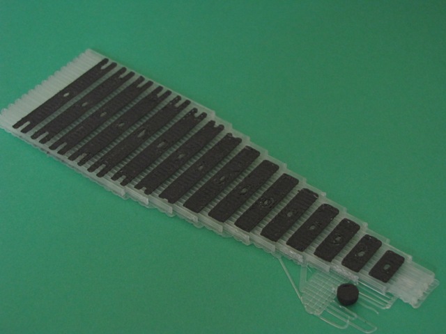
    Spring leaves are very thin.  The BFB-3000 software provides a selection of three Z layer print thicknesses, 0.125, 0.250 and 0.05mm with a target leaf thickness of 0.020".  The above three samples show results of the three Z layer thickness prints from left to right.  The 0.125 layer has thin outlines and disconnected fill at various points.  The 0.25mm thickness in the middle has good outline and fill while the 0.5mm print at right has ragged outlines and smearing of the critical center holes.
     The smearing and ragged outlines of the 0.5mm layer are shown above.
    By contrast the 0.25mm Z layer print in the middle has good outline, fill and center hole definition.
    Although the outline of the 0.125 Z layer print is good, the fill is incomplete.
    As a final step, removal of all three was done to determine the usefulness of the versions.  The 0.125mm layer at left can be removed but the larger springs with the notches proved impossible without breaking.  The 0.25mm layer in the middle were all successfully removed largely by flexing the raft and support with an occasional use of a model knife to pry loose small regions.  The 0.5mm Z layer version at right had too much adhesion and proved impossible to remove without breakage.
     The 0.25mm layer spring was assembled on a riser and a cover placed on in the photo above.  The spring assembly can be done without the need to grind away residue clear PLA support material.
     Three different build methods are shown above.  At left is the most recent build with the leaves flat on a clear PLA raft and support.  The middle assembly has the leaves printed flat and then sanded to remove the residue raft and support material and the one at right had the leaves built on their side.
    The build flat on clear PLA raft above looks and works good and fits well on the riser.
    Although the spring assembly with sanded away green ABS residue looks fairly good, the extra step of sanding opens the door to damage for these very small parts.  This version also looks and works good.
     The version with the spring leaves built on their side results in thicker leaves that are a bit more ragged in outline definition and require more trimming than the PLA raft version.
   
    The assembled PLA raft version in close up reveals the clear residue that was left in place.  It does not interfere with spring operation, however, four leaves were left out so that the stack would fit under the spring clamp.
    Above is the ensemble of spring leaves built flat on PLA raft along with the riser and clamp at the right.  Center hole and slot definition are all good.
    The spring leaves, riser and clamp are all very small parts as can be seen in comparison with a ruler.
     Nearly invisible at right is the raft upon which the springs were built.  No discernible residue remained on the raft and the raft was essentially intact after spring leaf removal.
    The above photo shows a partially assembled spring assembly with several leaves slipped on the post of the riser.  They fit well and are not overly loose.
    The whole set of spring leaves is shown above installed on the riser post with the clamp at right.
    The clamp will be glued over the spring assembly on the riser to retain the spring leaves in place.  Eight assemblies are needed, one for each driver.  The slots will accommodate the top of the trapeze levers that will connect the spring to the frame or equalization levers.

Saturday, January 7, 2012

Locomotive Springs

    The previous blog post showed results of fabrication efforts of the locomotive spring leaves.  Leaves have been built on the side edge and on the flat of the spring.  Above is shown spring assemblies of those methods.  The closer spring assembly was fabricated on side edge while the further one was fabricated down flat.  The leaves built on edge have varying thickness and must be at least 0.03" thick which results in fewer leaves and a noticeably stiffer spring assembly.  The ones built flat are 0.020" thick which results in a lower stiffness judged to be more realistic for this model.  The side built leaves have poorer hole and slot definition.  The flat built ones required sanding to remove the green ABS residue.  It is easy, but tedious to remove, but doable.
    An attempt to build springs vertical was also done, examples are shown above.  These exhibited very poor definition of holes and slots.  The BFB-3000 printer cannot easily fabricate the narrow strips of material close together as needed around the holes and slots.  This leads to badly distorted unusable parts.
    A second run of leaves printed flat was attempted using the small amount of green ABS left which resulted in a very poor raft structure, probably due to the difficulty the printer had drawing the small amount of remaining ABS on the spool.  This was attributed to the high spring force of the ABS.  The machine was re-loaded with clear PLA to make rafts and support structures.  The first run with clear PLA and flat spring leaves is shown above.
    The leaves were readily removed using care, mostly by flexing the raft by hand.  The smaller spring leaves popped off while the larger ones needed a bit of coaxing using a model knife to pry loose small portions that wanted to stick.  The leaves had good definition and only a very thin layer of clear PLA residue remained on the leaves.  They may be usable without the need to sand off the residue.
    The spring leaves are to be mounted on the spring riser and clamp parts with the holes in the spring leaves fitting over the post on the middle of the riser.  When checking for fit it was discovered that this set of spring leaves have overly small holes and will not readily fit over the post.  Rather that run the risk of breaking the post, the design was modified to increase the hole dimensions for better fit.  It takes near 3hr to fabricated a set of spring leaves.

Thursday, January 5, 2012

Locomotive Springs

    Locomotive springs are connected to the driver bearings using a riser that straddles the frame and rests on the top portion of the bearing in slots.  The spring leaves are clamped on top with a small frame to hold them in place.   The above photo shows four sets of spring risers and clamps.  The riser has a small vertical rod that passes through the spring leaves to hold them in place.  The support material is green ABS and the parts are black ABS.
    After removing the bulk of the support material small residue strips are visible on the inside of the riser and top of the spring clamp.   One set at left shows the arrangement of the two parts.  The clamp will be glued in place after the spring leaves are installed on the retainer post.  The spring riser will be inserted into the slots on the top of the bearings, but will not be glued in place.  Equalization rods will apply pressure to both ends of the springs holding the assembly in place on the top of the bearings.  The rods will be held to their respective attachment points with small machine screws.
    During early testing with the BFB-3000 printer spring assemblies were built using interleaved spring leaves.  The interleaving process did not work well as the spacing between the leaves did not permit meshing the two halves of each assembly.  Consequently on this trial individual spring leaves were fabricated adjacent to one another laying on their sides as shown on the raft/support structures above.  The spring leaves had a number of issues such as difficulty in removing them from the supports, uneven thickness that would prevent them from stacking correctly and incomplete build of the black ABS on portions of the spring leaves.
    At right of the above photo are the separated spring leaves.  They are not at all satisfactory so another attempt was done by designing a version that lay flat on the top of the raft structure as shown at left.  Those leaves were more uniform in thickness and had good shape definition.  They were readily removed from the support but as has been seen on other runs had strips of green ABS across the bottom of each spring leaf.  Removal of the residue support would be tremendously difficult considering the very thin leaf so this method also proves difficult to consider, but is better than building the leaves on their side as was done above.
    The presence of the green ABS residue prevented a full set of leaves from fitting within the clamp portion of the spring riser.  The picture above shows a partial set assembled as is intended.  The springs work and have a spring pressure about as expected!.   The tops of the spring clamp have support residue that will be removed using the Dremel tool later.  
    Above is shown the assembled partial spring leaf stack in the holder at the top of the riser in place in the slots in the bearings.  The assembly has good clearance and moves freely.  The left end of the spring lies directly above a mounting hole in the frame for a trapeze rod that attaches to the spring above.  The right end of the spring will also attach to a trapeze rod that straddles the frame and attaches to an equalization lever that lies below in the middle of the frame.  None of those rods have been built yet, however, during initial test runs similar rods were successfully built for the trailing truck spring assembly.
    Another method of building the spring leaves will be to build them on end without the use of any support material.  Similar vertical thin wall items have been built and this method will severely limit the amount of green ABS support in contact with the spring leaves.  The leaves will be limited in width to that value imposed by the printer resolution, 0.025" or more.  The leaves shown in the above photo are 0.02" thick and have some 0.01" thick residue stripes across.  The spring assembly thickness is 0.325" consequently about thirteen 0.025" leaves can be contained in the clamp.  The longest leaf is just short of 2".  The leaves are 0.25" wide.  These dimensions give some idea of the ability of the BFB-3000 to fabricate small parts.

Sunday, January 1, 2012

Fit Testing Drivers to Frame

    Efforts during the past months have now culminated in fit check assembly of the central driver portions of the frame to the driver sets.  The above 3D CAD illustration shows a top view of an assembly of the various drawings used to fabricate the parts as they should appear when assembled.
    The three central frame sections (FDS, MIDS and BDS) are glued together while all other parts have sliding fits permitting rotation of the drivers within their bearings and sliding of the bearings up and down in their frame slots.  The bears are retained by the pedestal binders which are screwed in position.
    The last part to be fabricated was the Back Driver Set.  The set consists of the two drivers, the bearings, the axle and the pedestal binders.  Each of the parts above was separately fabricated in the BFB-3000 printer.  The longest run time was for each driver at some 3hr+ each.  The green ABS is the raft and support material for the parts which are fabricated in black ABS.  The green supports must be removed before the driver set can be used.
    The first step consisted of using a needle nose pliers or hands to pull away the majority of the support material.  Residue of the support ABS are stripes that adhere to portions of the parts.
   The second step is to further remove portions of the stripes that are suspended between portions of the parts, particularly the drivers.  That removal is done using a needle nose pliers.  Some cutting with the model knife was also used to trim portions where feasible.  The result still leaves attached residue segments of green ABS.
    The stripes of green support material tend to form small ridges on the black part.  Some can be cut away, but that has proven very time consuming and not easily done.  The residue strips of support adhere tightly to the black part material.
    The final steps of residue removal is grinding away using a Dremel sanding wheel.  That proceeds smoothly although the tool must be used carefully as the plastic is easily ground away excessively.  The final result of part clean up is shown above.  
     The Back Driver Set is assembled above.  The bearings are slide unto the axle after installing one driver.   The bearings have an outside and inside that differ.  The two pedestal binders will be installed after the driver set is installed in the frame.
    The above photo shows a collection of the parts that form the central driver portion of the frame and the driver sets.  
    The first step in assembly is to place the frame on it's back and slide the bearings of each driver set into their respective slots.  The set of pedestal binders is shown with 1-72 temporary screws in place ready to install on the frame.
    The next step is to screw the pedestal binders in place.  All are the same except those for the Main Driver which are slightly longer to provide space for the larger main axle.  The screws used here are self threaded in place for now.  They are undersized #1-72 screws.  The frame will be drilled and tapped later for #2-56 screws.
    The fit check assembly of the drivers and frame is shown above.  The drivers turn freely and the bearings slide up and down in the frame slots freely.  The black ABS parts will receive touch-up flat black paint to hide remaining sanding and cutting marks later.
    At this point the central driver portion of the chassis has been completed except for paint touch-up and appropriate threading for the final attachment screws.  There remains both front and rear portions of the frame to build and fit.  The front portion is the Pilot-Cylinder Section (PCS) that will mount the cylinder block, front platform and cow catcher and ride over the pilot truck.  The back portion will be possibly one or two sections that mount the firebox and cab and ride over the trailing truck.
    Other parts associated with mounting the valve gear and boiler will be glued to the chassis frame later as well.  Along with the side rods and valve gear many, many parts remain to be added to the portion completed so far.  Of course later the boiler and cab assemblies will be added as well.  These too will need to fabricated in sections to remain within the working volume of the 3D printer.

Friday, December 30, 2011

Adding The BDS To The Frame

    The Back Driver Section (BDS) is a bit less than 4" long and took 18hr 36min to print.  The significant amount of green ABS support and the need to switch extruders on each of many layers drives the print period.  The back end of the BDS section is at the top.
    The support material removed in a manner similar to the other frame sections leaving stripes of green ABS attached where the support material came in contact with the black frame.  Removal is done with a model knife.
.  
    Once the frame has been cleaned up it is ready for attachment to the other two sections previously assembled.   Before assembly the new section is held in place using rubber bands to check fit and dimensions.  Small adjustments were made by removing material at the joint to square up and set the driver to driver distance.
 
    During gluing with CA various tools were placed on top to hold the frame solidly on the glass desktop.  The ruler shown was used to verify that the frame was straight from front to back.  Rubber bands are just visible at the rear holding the new BDS to the rest of the frame.  The ruler is 15" long.
    After the tools were removed the rubber bands are readily visible.  The band and red plastic wedge at the top side in the photo were used to tension the frame with a bit if side pressure to hold it straight aligned to the ruler.  You might be able to note that at this point the frame is 12" long.   The three sections (MIDS, FDS and BDS) are half of the frame sections that will ultimately be included.  This portion contains the four sets of drivers.
    The three parts of the frame are each built with integrated sub-parts such as cross braces and the brake hangers.  Some of the larger cross parts such as the link supports and boiler mounts will be separately added as they are fairly large and would have made the build of the frame sections unwieldy.  A fourth set of drivers is being fabricated to complete the ensemble.  Previously the Front, Intermediate and Main driver sets were built and shown.  The Back set is the fourth.  Once all drivers sets are ready and fitted, the frame will be drilled and tapped for the pedestal binders and they will be attached with screws.
    Design effort is underway to complete the frame sections over the trailing truck.  Much of that design work was done prior to the BFB-3000 3D printer arriving.  It may need to be subdivided into two sections as has been contemplated, although it would just barely fit within the Z height capability of the printer (8 1/4").   The combined Back Frame Assembly is about 8 1/8" long as currently designed.  The trailing truck equalizer lever mount needs to be designed.  It is located on the frame about half-way between the small mounting bracket at left center and the left front of the frame.
    The back frame slides into slots on the main frame and gets bonded in place.  The trailing truck rides under this frame section supporting the firebox end of the boiler and cab.  Other moving parts also attach to the back frame including the truck spring mounts, springs and equalization lever and rods, and centering spring.  The above design assembly does not yet show the equalization lever mount, both equalization rods or the centering spring assembly.  Once the back section is added the frame will be about 18" long.
    Another part of the frame is located up front, the Pilot and Cylinder Section (PCS) frame.  That portion will add about 4" more to the front.

Thursday, December 29, 2011

Pedestal Binder Fabrication, Clean-up and Fit Checks


    Additional pedestal binder bars were fabricated, three identical sets for the Front, Intermediate and Back driver slots and a slightly longer set for the Main driver slot.  The Front driver set is shown cleaned up ready for use while the remaining three sets are still attached to the raft/support structure.  The binders are easy to remove by hand but do have a series of stripes of residue support material that required removal by sanding with the Dremel sanding wheel.
    The above photo shows the slight difference between the Main driver slot binder at the top with one of the other three binder sets.  The difference is small.  The wider Main driver slot accommodates the larger diameter bearing and axle.
    The binders were trial fit using undersized 1-72 machine screws.  The screws for final assembly will be 2-56 after the frame is tapped.  The smaller screws fit snug enough in the pilot holes to stay in place, but have little strength.
    The Front driver set is shown with binders secured in place using the 1-72 machine screws.
     The remaining sets of binders for the existing portion of the frame consist of one set for the Intermediate slot and one set for the Main slot.  The Main slot binder is slightly longer.
    The machine screws were first run into the binders flush with the mating surface.  In one or two cases the holes are almost loose.
    The frame holes are slightly smaller and require slight force from a small #00 Philips screwdriver to drive into the frame holes.  Care was taken to avoid over-tightening and removal of material so that later tapping with the 2-56 tap will be more firm.  The Intermediate driver set is shown above installed with binders held in place with 1/72 machine screws.
The Main driver binders were also installed in a similar manner.  Note that all drivers now have residue material removed and are ready for painting as are the binders and frame assembly.  At this stage the overall assembly can be handled without having driver sets fall out.  The drivers have a noticeable amount of vertical play which will allow the spring equalizer systems to work when the wheels move over uneven track as in the prototype.  None of the spring equalizer system is yet installed, however, the bearings have slots to mate with the spring brackets and the brake hangers have holes for the beam fulcrums.  

Main Driver Residue

    The main driver set was taken apart (not yet bonded with glue) and residue support material removed.  The bearings and axle had already been sufficiently cleaned.  The inside of each driver needed sanding with the Dremel tool and minor touch-up with the model knife before reassembly.  Drivers will not be glued at this point until all chassis frame fit checks are complete.