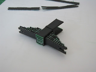
Locomotive springs are connected to the driver bearings using a riser that straddles the frame and rests on the top portion of the bearing in slots. The spring leaves are clamped on top with a small frame to hold them in place. The above photo shows four sets of spring risers and clamps. The riser has a small vertical rod that passes through the spring leaves to hold them in place. The support material is green ABS and the parts are black ABS.
After removing the bulk of the support material small residue strips are visible on the inside of the riser and top of the spring clamp. One set at left shows the arrangement of the two parts. The clamp will be glued in place after the spring leaves are installed on the retainer post. The spring riser will be inserted into the slots on the top of the bearings, but will not be glued in place. Equalization rods will apply pressure to both ends of the springs holding the assembly in place on the top of the bearings. The rods will be held to their respective attachment points with small machine screws.
During early testing with the BFB-3000 printer spring assemblies were built using interleaved spring leaves. The interleaving process did not work well as the spacing between the leaves did not permit meshing the two halves of each assembly. Consequently on this trial individual spring leaves were fabricated adjacent to one another laying on their sides as shown on the raft/support structures above. The spring leaves had a number of issues such as difficulty in removing them from the supports, uneven thickness that would prevent them from stacking correctly and incomplete build of the black ABS on portions of the spring leaves.
At right of the above photo are the separated spring leaves. They are not at all satisfactory so another attempt was done by designing a version that lay flat on the top of the raft structure as shown at left. Those leaves were more uniform in thickness and had good shape definition. They were readily removed from the support but as has been seen on other runs had strips of green ABS across the bottom of each spring leaf. Removal of the residue support would be tremendously difficult considering the very thin leaf so this method also proves difficult to consider, but is better than building the leaves on their side as was done above.
The presence of the green ABS residue prevented a full set of leaves from fitting within the clamp portion of the spring riser. The picture above shows a partial set assembled as is intended. The springs work and have a spring pressure about as expected!. The tops of the spring clamp have support residue that will be removed using the Dremel tool later.
Above is shown the assembled partial spring leaf stack in the holder at the top of the riser in place in the slots in the bearings. The assembly has good clearance and moves freely. The left end of the spring lies directly above a mounting hole in the frame for a trapeze rod that attaches to the spring above. The right end of the spring will also attach to a trapeze rod that straddles the frame and attaches to an equalization lever that lies below in the middle of the frame. None of those rods have been built yet, however, during initial test runs similar rods were successfully built for the trailing truck spring assembly.
Another method of building the spring leaves will be to build them on end without the use of any support material. Similar vertical thin wall items have been built and this method will severely limit the amount of green ABS support in contact with the spring leaves. The leaves will be limited in width to that value imposed by the printer resolution, 0.025" or more. The leaves shown in the above photo are 0.02" thick and have some 0.01" thick residue stripes across. The spring assembly thickness is 0.325" consequently about thirteen 0.025" leaves can be contained in the clamp. The longest leaf is just short of 2". The leaves are 0.25" wide. These dimensions give some idea of the ability of the BFB-3000 to fabricate small parts.


No comments:
Post a Comment