Thursday, December 22, 2011

Continued Adjustment of Wheel, Axle and Bearing Dimensions

    The recently built the adjusted axle, intermediate drivers and bearings are shown fitted to the MIDS frame section.  The wheels fit snugly to the axle making alignment less of a problem.  The bearings fit well on  the axle allowing free rotation without binding.  The only issue is that the bearings fit too loose in the frame slots allowing excess fore and aft motion which could be a problem with the operation of side rods later.   The width of the bearing portion that fits the frame slot will be increased slightly to promote a better fit.  The frame dimensioning is correct to the main plans.
    All the parts were built with black ABS on a green ABS raft with raised support for the parts.  This practice allows relatively easy removal from the raised support rather than the more solid raft which holds so tightly that removal is extremely difficult or impossible.  The bearings rotate freely on the axle, the wheels fit snug on the axle.  The right hand wheel shows the result of grinding away the remnants of green raised support material using a Dremel tool and drum sanding wheel.  The surface is smooth and will be painted with flat black enamel before glue assembly.  The drivers are 2.625" diameter over the tires that contact the rails and spaced 2.2135" between inside surfaces.  Both of these dimensions are 1/24th of the prototype dimensions on the USRA plan for a heavy Mikado.  The rails will be spaced 2.354" (59.7958mm) for a scale 1/24th guage.  This is larger than G gauge which is 1.772" (45mm) so a custom section of track will be built to display and test the models moving parts.
     The intermediate wheel, axle and bearing set above is partially disassembled with the axle remaining inserted into one wheel.  All the above parts have be cleaned up ready for painting with flat black.  At this moment only those portions of the parts that were sanded or carved will be painted leaving the original black ABS on the outside of the wheels, portions of the bearings and all the axle except one end that was attached to the ABS support during the build.

     The above parts are the main axle and bearing set.  The main axle dimensioning was adjusted the same amount as was done for the intermediate axle and came out almost exact on scale dimension.  The Front, Intermediate and Back axles are identical to one another and have a prototype dimension of 10" while the main axle has a 12" diameter.  The bearings for the main are correspondingly larger to accommodate the larger axle.  The bearings came out a bit too large on the width that comes in contact with the frame slot, so that dimension will be reduced a bit and the parts re-built.  The green ABS support structure has been removed from the parts but small residue remains to be cut or sanded away as they will not simply pull away as the majority did.  The main driver wheel designs are complete awaiting their turn on the printer for build.  Their axle hole ID has been adjusted by the same amount as has been done for the Front, Intermediate and Back drivers which should cause them to fit snug on the main axle.
    The clam-shell holding fixture above was built to hold the axles for the Front, Intermediate and Back drivers, provide a space to contain the bearings during the assembly process and precisely gauge the wheels during gluing.  This fixture has been used to assemble several of the earlier build attempts to verify the process.  Another similar fixture for the main axle, bearings and drivers will be built with all dimensions the same except for the half-round end holes in the middle to accommodate the larger main axle.
    The axle with bearings mounted is installed in the half round apertures at the ends.  The wheels are shown in rough assembly above to illustrate the scheme.  Then the clam-shell is closed and held snug with rubber bands.
    The rubber band around the clam-shell keeps the axle and bearings in place provided the pressure to remove a wheel for gluing is not excessive.  Each wheel is removed and a small amount of Cynoacryalate (CA) applied near the outer end of the axle and the wheel carefully installed with the axle end flush with the surface of the wheel center rod crank.  Then the process is repeated on the other wheel.   After gluing both wheels additional rubber bands are applied to hold the wheels firmly to the fixture while the CA cures.

Tuesday, December 20, 2011

Adjusting Tolerances of wheels, axles and bearings

    Tolerances between axles, bearings and wheels need adjusting.  Shown above are several iterations of each shown alongside the MIDS chassis.  Essentially three iterations of wheels and axles have been done and five trials of the bearings.  Alternate materials such as PLA and ABS have been tried and two Z layer thicknesses.  Almost all changes resulted in changes in key interface dimensions.  
    Shown above are the three most recent trials of black ABS axles.  On the left is one made with 0.125mm Z layer while the other two were made with 0.25mm Z thickness.   All three were built on top of a 0.25" thick green ABS support layer above the thin raft section to improve ease of removal.  The support layers are run in accordion folds which reduces the contact with the part.  The base raft comes out almost solid which increases adhesion greatly making removal very difficult.
    The middle axle is slightly undersized and the right hand axle has adjusted diameter which gets the part very close to the desired scale size, 1/2" per foot of a 10" prototype diameter (1/24th scale).  Indents on the ends provide a ready means to key the drivers to 90 degrees as done for steam engine drivers.  This axle is used for Front, Intermediate and Back drivers.
    A slightly larger 12" prototype diameter axle is used for the Main drivers, so another set of iterations to achieve correct scale size will likely be required for that axle and probably the wheels and bearings as well.   The Main drivers also have a much larger more complex side rod shaft structure to fit the side rods, main rod and eccentric rod.
    The original bearings built were PLA shown on the assembled driver and axle set at the top of the picture above.    These were difficult to clean up so a pair of ABS bearings were built, at photo middle.  Those bearings fit OK on the PLA axle but are a bit undersized for the design axle diameter.   Consequently a third set was built with adjusted axle hole diameter as shown embedded in the green ABS supports on top of the thin solid layer ABS raft base layer.  
    Also, the width of the bearing slot was a bit too liberal providing too much looseness to the frame slots.  Measurements confirmed that the bearing slot is too narrow while the frame slot is correct.  The new bearings still remain to be removed from the support material, cleaned up and checked for proper fit with both the final axle and frame. 
    The wheels also have undergone adjustment.  Above right is a PLA wheel, the green middle being ABS and the one at left black ABS.  The PLA wheel came out good, but the approach was to use black ABS.  Once the black ABS material arrived, the left wheel, an intermediate driver, was made using the dimension adjustments of the green Front or Back driver above.  The difference between them is the larger counterweight of the intermediate driver.
    Both the green ABS and black ABS wheels were built on thick ABS supports reducing contact with the ABS solid raft.  This approach greatly reduces contact adhesion permitting relatively easy removal from the raft-support structure.  The photo of the bearings above shows one such structure.  The bearings are not directly in contact with the raft but ride instead on several layers of accordion fold support structure that is much easier to separate from the part.  This approach has proven superior to using a PLA raft and support approach.
    Adjustments will continue of the above parts until good appropriate fits are achieved for axles, wheels and bearings with the frame slots.  These are the key moving parts and must fit well to permit good operation of wheels with the side rods and bearings with the equalization scheme.
    A conclusion reached after using the 3D printer is that accuracy to design dimensions is not of the order achieved using metal machining and requires small adjustments to correct for the build software (Axon) conversion process.  The repeatability is good so that once adjustments are incorporated, multiple parts may be built and achieve comparable accuracy.
    Code 250 rail, ties and suitable spikes have been ordered to permit build of short sections of track for use in checking rolling operation of drivers and other parts.  In the end a suitable length of track section will be built and finished with ballast and appropriate coloring for display of the finished locomotive and tender.

Saturday, December 17, 2011

Test Assembly of MIDS with Wheel Sets and Bearings

    After cleaning up the MIDS frame a test assembly was made using two of the wheel-axle sets with bearings that were used to check glue procedures.  One set was black PLA while the other had green ABS drivers with the balance being black PLA.  The green driver set are actually Front (or Back) drivers instead of intermediate drivers as should be in that location.  The rear slot should be occupied with a main driver set, not the Front (or Back) set used here.
    The principle concern was whether the bearings would fit well between the frame internal surfaces and slide freely up and down and whether the wheel tire would line up properly with the brake hanger slot.  The bearing outside surface in contact with the frame was a bit too wide causing binding in the slot.  It would fit but required too much pressure to permit freedom to slide.  This is being corrected by building additional bearings that will fit Front, Intermediate or Back driver axles.  Later a set of main bearings will similarly be modified with a similar thinning of the outside flange on the bearing.
    The above photo shows a top view of the assembly with the bearings in the slots.  The portion of the bearing showing is the inside flange.  The spacing between the flanges is a bit too tight also, so the new bearings being made feature a wider slot between the bearing flanges to loosen up the fit with in the frame slot.
 
    The front view shows the frame spreaders located behind the bearings of the intermediate and main drivers.  The clearance between the spreaders and bearings is adequate with no contact.  The parts used here are fairly close to prototype configuration with minor adjustments of size for the 3D printer tolerances.  The parts look to be scale and generally have quite good agreement with scale dimensions.
    The next step will be fabricate both intermediate and main drivers, axles and bearings, assembly those and install in the MIDS frame assembly.  They will be built in ABS except the axles which come out much better in PLA.
    The size of the above assembly is approximately 5 1/2" long by 3" wide by 2 1/4" high.  One part that was omitted is the rear link brace which also provides a boiler attachment.   That part would have greatly complicated the support structure, so was deemed better to be built separately and attached to the frame.  I attaches directly centered between the two brake hangers with an "L" shaped bracket that is ideal for gluing. A test version of that part also needs to be made to validate dimensions, adjusting if necessary to get a good fit.

Removal of Support Material from MIDS Frame

     The large pile of green ABS support material behind the MIDS frame shows the relative volume of support vs the black ABS part.  The support came away relatively easily using fingers and a needle nose pliers.  Some small portions of green ABS remain attached and will require use of side cutters, file or model knife to remove. Small white bond lines between the green ABS supports and black ABS model are visible.  These will require paint touch-up after filing the area smooth.  
    The frame above after support removal seems to fairly closely represent the 3D design.  The advantage of building an integrated assembly is the accurate alignment and strong bonds between the sub parts.  This part is composed of two side frames, two spacer frames and two brake hangers for the intermediate drivers.  The large slots at the front of the picture are for the intermediate driver bearings while the slots at the rear are for the main driver bearings.  Frame keeper bars will be bolted across the bottom of the open slots to retain the bearings in place as is done on the prototype locomotive.
    The results of the lengthy 22hr 24min print effort are fairly good.  The model part will be measured to determine if it is usable as is or requires some modifications to result in adequate fit with the drivers and other parts that will attach to the frame, and mating with the frame portions forward and rearward.

Friday, December 16, 2011

Printing the Vertical MIDS Frame Assembly


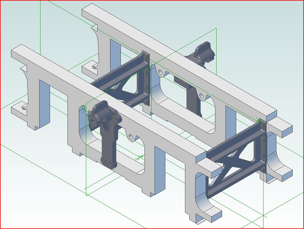
    Using the vertical build method the above assembly was designed.  It consists of right and left Main @ Intermediate Driver Section (MIDS) frames, the two frame spacers in proper position and the two brake hangers in position.  The overall assembly is 2 3/4" wide, 4 3/4" long and 1 1/2" high.  By building it as an assembly it becomes an integrated whole and does not require any jigs or fixtures to make it square and true while applying glue.  This kind of assembly was contemplated originally, and temporarily abandoned when horizontal builds of this length could not be make successfully.
    As was done for the single side frame member vertical build the Axon software for the BFB-3000 3D printer defined a large array of support material around the part.  The part was built in black ABS with green ABS raft and supports.  You can just make out one of cross braces between the vertical side frames.  Also, the two brake hangers that are located between the intermediate and main drivers are visible midway up the outside of  the frames.
     The bottoms of the frames have the frame keeper attachment features and the pilot holes for the small bolts that will be used to hold the keepers in place.  Each keeper provides continuity across the bottom of the frame below the slots where the wheel bearings are located.
    This view of the printed assembly prior to removal of the green support material shows the top or front of this portion of the frame and the cross brace that is located just after the intermediate driver slots.  Another cross brace is located following the main driver slots which are at the bottom of the print assembly, or more rearward on the frame.  The driver order is Front, Intermediate, Main and Back.  The Front and Back are identical while the Intermediate and Main differ with larger crank axles and in the case of the Main a larger wheel axle and bearing assembly.
    The next step will be to remove the green support and raft material hopefully avoiding damage to the black MIDS frame assembly contained within.

Thursday, December 15, 2011

Removal of Supports On Vertical Frame Model

    The vertically built mid frame section is essentially surrounded by support material.  Both the supports and part are green ABS.
    Removal was not as difficult as was first thought.  Much of the supports came out as if accordion folded cardboard leaving the part relatively clean.  Small whitish strips were left where the thin support pieces contacted the model.  Most of them were narrow and nearly flush with the model surface.  In a couple of areas a bit of filing or sanding may be required to make the region smooth.  This model part was built at 25% density and is somewhat fragile.  The dimensions however were very close to the design files eliminating the need to adjust the size.  The orientation of various holes were such that the printer could not make them round.  That should not be a problem as it is intended to use drill and tap to prepare those for some attachment bolts.  Those will permit partial disassemble of the model when necessary later.
    This frame piece is a test part and subsequent tests will attempt to build the much of the center frame completely assembled with cross braces and the brake hanger pieces.  This effort will also be conducted with a vertical build.

Wednesday, December 14, 2011

More Efforts To Build Chassis Frame Parts

     The front main chassis was divided into four approximately 4" long sections.  A pair of one of the sections was printed using PLA raft and ABS parts, no supports were required.  As can be seen above, even the relatively short sections of ABS warped significantly when printed horizontally.  The chassis frame must be straight due to it's close fit with many other parts.  The amount of warp above will not work.
    Another attempt was made with one of the frame sections standing vertical in the printer.  This meant many support columns to deal with the many overhangs present with the part in this orientation.  The picture above shows the part still embedded in ABS support material.  In this print example, the raft, support and part are all ABS.  More than likely removal from the supports will be problematic as all are the same color.  An order of black ABS just arrived so in future the model parts will be black ABS or PLA and raft and supports will be of a contrasting color.  The as printed part looks like a model of a skyscraper, most of the vertical walls are the outer portions of supports.  The BFB-3000 printer can readily lay thin section vertical walls in place with good alignment layer by layer.  Hopefully the part can be separated non-destructively.  At first glance the part looks square and does not appear warped in any degree.  This may be due to the fact that it is free standing with no material with a different coefficient of expansion in tight contact.
    Perhaps it would work reasonably well to use ABS supports and a PLA model, or vice.  Alternates will likely be tested to determine the overall best approach for the complex vertical models of the frame.