Tuesday, August 28, 2012

Engine Drive Rods

Revised:  8/28/2012          Subject To Revisions


Design of Drive Rods - Cam Lock Attachment Method

The author examined the sizes of the drive rods and learned that making them close to prototype configuration would provide very few threads to attach the front or rear drive rods (side rods) to the intermediate rod.  Each side of the locomotive engine has a three articulated section side rod.  The middle intermediate section connects from the main (third) driver to the intermediate (second) driver just ahead of it.  Ahead of the intermediate rod the front drive rod connects from the intermediate rod extension to the front driver.  Behind the intermediate rod the rear drive rod connects from a intermediate rod extension to the fourth driver. 

Fireman Side Drive Rod Set

The front and rear rods pivot on the intermediate extensions allowing all four drivers to move up and down over track undulations while maintaining full traction force on the track.  The equalization spring system also allows each driver as well as the pilot and trailing trucks to balance their respective traction or down force while moving along uneven track.  The intermediate drive rod has to extended thin "I" sections with holes to accept a mating "Y" section with holes of the respective end rods.  Ahead of the intermediate   Although this is not a working model, the author wishes to make it as prototypical as possible fully testing the 3D printer's capabilities as possible.

Front Drive Rod Section

Because the arms of the "Y" on the front and rear drive rods are very thin (0.04458"), very few if any threads could be made on the inner arm that travels very close to the driver.  No room for a separate nut.  Even an 0-80 screw would have just 3.6 threads.  In the ABS plastic this would be asking a great deal to either make the threads or have them survive several insertions and removals during the balance of design, build, fit checks, disassemble and assembly operations.  Further, a fairly precision washer (~0.099" thick X ~0.213" OD X 0.066" ID) would be needed between the "Y" arms to prevent collapse or over tension on the inserted "I" section else the sections would not freely rotate as in the prototype.  Standard washers don't fit the bill.  Specials might be made on the Sherline lathe with much difficulty.  Overall the screw and washer idea were not at all interesting.

"Y" Section End of Front or Rear Drive Rod

A cam lock mechanism was envisioned that would permit the parts to be joined and permit rotation motion as in the prototype while transferring the thrust between the intermediate rod and the two end rods.   The cam consists of a truncated round section inside the "Y" section of the end rods that when turned at right angle to line up with the bottom opening in the intermediate "I" section will pass through putting the round cam inside the round opening. 

Cam Lock Arrangement Showing Insertion Angle

The end rods are then rotated putting the round portion of the cam into loose contact with the matching round section of the intermediate "I" section.  Thrust of the intermediate rod is then passed through the round sections between the rods.  Each end rod can also rotate up and down allowing the respective driver to follow uneven track as necessary.

Front Drive Rod With Cam Fully Engaged 


Front Drive Rod During Rotation Into Position 


Front Drive Rod At Normal Position
 
Rear Drive Rod Before Engagement

Rear Drive Rod Cam Engaged Being Rotated Into Position
 
Drive Rod Assembly

Building the Drive Rods with the 3D Printer - First Trial

The first thought regarding orientation in the printer was to place a full set of driver rods upright so that the cams and "Y" walls would not require much support material.  Support material and residue inside such narrow openings is difficult to remove.

Set of Rods in 3D Printer Prior To Removal

The rod set took 4hrs 9min to build.  Most of the support material was below  the rods.

Close Up View Of Rod Set In 3D Printer

Close up inspection in the printer revealed that the near end support material separated during the print perhaps leading to the distortion observed on the intermediate rod ends above.

Rod Set After Removal From Printer

 After removal the other ends of the intermediate rods also shows distortion probably due to the rather short thin section.  There was no support material separation on this end.

Rod Set  Showing Distorted Ends On Intermediate Rods In Middle 


Distorted Intermediate Rod Ends

The ends of the intermediate rods with the separated support material shows the greatest amount of distortion of the Cam-Locks.  They look unusable at this point. 

Front and Rear Rods "Y" Sections At Sides 

 As planned the "Y" ends of the front rods containing the Cam portion shows good definition.  They look to be directly usable without need of any clean up.

Rear Rod Ends Have Good Definition of Arms and Cams

The rear rod "Y" ends also have good definition and are clear of support material as planned.

 
Complete Rod Set After Removal Of Support Material

Removal of support was mainly done by hand with a small amount of needle nose pliers and model  knife application.  The Cam-Locks on the middle intermediate rods are mostly unusable without further shaping.  Some of the ends are so bad they cannot be adequately re-shaped.

View of Poorly Shaped Cam-Lock Ends on Intermediate Rod "I" End Sections

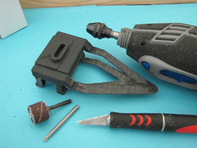
A couple of the intermediate rod ends can be re-shaped using model knife and Dremel sanding wheel.
This was done to do trial fits of the end rods.  While doing the trial fit it was discovered that the "Y" sections were too tight.  The design files were revised to loosen up the tolerances of "Y" sections relative to the intermediate rod "I" sections and the cam diameter relative to the cam-lock diameter.

Building Drive Rods - Second Trial

The intermediate rod build file was revised to orient them laying down and applied to the 3D printer.

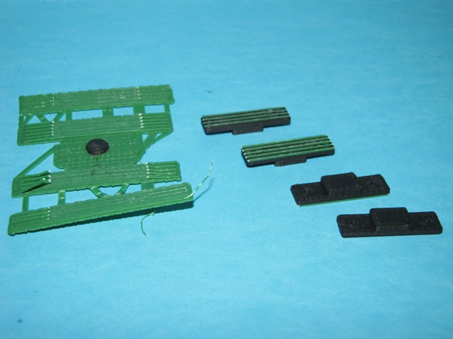
Intermediate Rod Set Built Laying Down Upon Removal From 3D Printer

The results looked much better than the previous trial.  Some loosening of the support is evident on the lower of the two rods in the photo, however, no discernible distortion of the rod is observed.

Sets of Rods Using The Previously Built End Rods and New Intermediate Rods 

With the good definition of the newly built intermediate rod cam-lock ends a good fit check was made using the prior built end rods.  The "Y" sections of the prior end rods needed loosening up which was done using a model knife.  The intermediate rods needed to have support material residue removed using the Dremel sanding wheel.  After those improvements the cams of the end rods would fit into the cam-locks of the intermediate rods OK.  The cam assemblies worked as planned allowing free rotation in the normal position while transmitting side forces between the rods.  A preliminary check of the hole sizes showed that they would need to be opened up a bit except for the main driver hole which fit fine.

Close Up Of The Cam Lock Arrangement Used To Join Drive Rods

Using the modified first trial end rods with the second trial intermediate rods works, however, the "Y" ends of the end rods are somewhat distorted, not round as they should be. 

Set of Drive Rods For Trial 1

Since the second trial intermediate rods have very good shape definition the author decided to make new end rods laying down also to take advantage of the better definition. The author was willing to put in the extra effort to remove the support material and residue inside the "Y" section that would occur.


New Front End Rods Built Laying Down Along With The Fit Check Set Just Discussed

A set of front drive rods was built which exhibited the planned better shape definition.  The design files were modified to enlarge the "Y" opening and reduce the cam size to provide a suitable fit with trial 2 intermediate rods.

Trial 2 Along Side Trial 1 Intermediate Rods

The improvement in shape definition is clearly evident in the above photo.

Trial 1 (Top Set) and Trial 2 Front Drive Rods

On the new front drive rod "Y" ends at right side of photo the residue of the support material can just be seen sticking out.  All the residue needs to be removed to achieve the design size.  This was done using a model knife with plenty of patience.

Rear Set of Trial 2 Rear Rods
 
A set of rear rods was also built laying down with adjusted "Y" and cam dimensions as was done with the front set.


Complete Set of Drive Rods For Trial 2

The front and rear sets of rods need to be removed from the support material as shown above.  The most difficult is removal of the material passing through the "Y" sections at the top portion of the rods in the photo above.  After support removal the residue was removed on the back using the Dremel sanding wheel and inside the "Y" section with a model knife.

The Complete Set of Side Rods For Trial 2

The completed rods were fit checked above and were found to work freely.  The cams installed readily and coupled in-line force as in the prototype rods well.  These should work out fine.  The holes or pins on the drivers need to be adjusted for proper fit.  Only the main drivers with the larger holes fit correctly.

Driver Set Showing The Cam-Lock Arrangements

In retrospect the cam locking scheme works fine but requires patience to remove the support residue from the end rod "Y" sections.  This method of joining the rods works very well freely allowing rotation and providing solid coupling between rods when they are rotated up to 45 degrees either side of in-line.

Adjusting The Rod Hole Diameters and Threading The Driver Pins

The next activity is fitting the drive rod set to the drivers.  As was stated previously the shafts on the wheels for the rods do not fit the holes in the drivers being a bit too large.  Further, each shaft section except the on the main drivers needs to be threaded for retainer screws.  In order to do the threading and driver modifications requires that the bulk of the locomotive be disassembled.
 
Partially Disassembled Locomotive. 

Disassembly involved removing the front frame with pilot, pilot truck, driver springs and frame keepers beneath each driver.  The photo above shows that in addition to removal, each driver set must be taken apart to support work on the driver in the drill press.

Drilling Driver Rod Shaft For 2-56 Tap - #50 Drill

Each of the front, intermediate and rear drivers needed tapping for 2-56 threads.  One quarter inch 2-56 screws with #2 flat washers will be used to retain the rods on the short rod shafts.

Dremel Drill Press and Tool Used To Drill Driver Rod Shafts 

The Dremel drill press and tool worked well with the small #50 drill called for to prepare for tapping 2-56 screw threads.

2-56 Hand Tap and Drivers 

A hand tap holder was used to make the small threads.  It works very easily without problems in the ABS plastic of the wheels. 

Sherline Mill Used To Drill Rod Holes To Fit Drive Wheel Shafts

The author's Sherline Mill was used manually like a drill press to enlarge the holes in the rods slightly.  This worked well in the plastic and did not require a holding fixture.

Author's Compliment of Power Drills Used For Project

The Sherline mill at left can be operated either manually or automatically as a CNC tool.  The Dremel drill press and hand tool at right were used for the smaller drill size.

Fit Check of Drivers and Rods

The sets of drivers and rods were fit checked to verify free rotation and proper clearance.

Disassembled Locomotive Frame and Parts

The photo above shows the stage of disassembly of the locomotive.  There are many, many parts in the model at this point.  The author designed many for disassembly to support operations such as the activity just carried out.

View of Disassembled Locomotive Frame


Another View of Disassembled Frame 


View of Fit Checked Driver Set Ready For Installation 


View of Inverted Frame With Drivers and Frame Keepers Installed

The reassembly calls for the drivers and their respective frame keeps to be re-installed first.

Locomotive Frame Upright Ready For Rod Set Installation


Locomotive With Rod Sets Installed 

Each rod set uses three screws and washers to retain it in place, one each in the Front, Intermediate and Rear driver.   In the above photo black screws were used with stainless steel washers. 

Another View of the Driver Rod Set in Place 

The locomotive mechanism moves freely at this point allowing the individual drivers to move up and down as on the prototype.  This was done to allow the locomotive to maintain traction on slightly uneven tracks as was usually the case for freight routes.

Fully Assembled Locomotive Motion Structure With Drive Rods


Closer View Of Assembled Locomotive With Drive Rods

The process of design, fabrication, adjustments, re-fabrication and final machining took the better part of several weeks working part time, even though retired.  The next step will likely be the pilot truck equalization mechanism.   This consists of a lever similar to those on the trailing truck and a pivot assembly.  The pivot assembly is located between the frame members under the cylinder assembly.  This will be done next to determine how it will be installed, removed or adjusted after the cylinders are attached. 

Thursday, August 16, 2012

Front Beam and Pilot Part

Revised:  8/16/2012          Subject to Revisions


The author decided to design the front beam of the locomotive to compensate for the rounding of the platform on the front chassis section that sits over the pilot truck.  On a previous blog post the rounding of the front chassis section was discussed.  Rather that reprint the part it appears easier to design the pilot beam with angled extensions and use the Sherline mill to modify the front platform to match.  The pilot or cow catcher portion of the front beam assembly is rather complicated having many small bars including angled bars that brace the pilot.  The design file on the Alibre CAD is one of my larger efforts.


The above part design may be printable on the 3D printer.  If so it will prove the real worth of the machine by building complex parts with many design features.  This design has 50 features with may faces (568), edges (1541) and vertices (1051).  This is the most complex part designed to date.  It will be bonded to the front of the existing front chassis section.


The very front of the front platform that sits behind the pilot beam is curved due to part shrinkage during printing.  The curves are outside the two main frame sections.  Between the frame sections the front platform is straight.  The design of the front beam and pilot part has the mating portions of the platform angled at about 9 degrees.  The front of the front frame portion (not yet attached to the main frame) will be milled to matching angles so that when the two are mated they will line up.  The milling will proceed after printing the pilot beam part in case further modifications will be needed.


The front beam and pilot part bottom rear view is shown above to more clearly show the angle straps that support the pilot and front steps.  It also shows the hollowed out portions of the beam.  Slight engineering changes were made to facilitate 3D printing.  These were done in a fashion that would meet prototype design principles.

After 13hrs and 2 minutes the front beam and pilot part was finally finished as shown above.  The part was configured by the Axon software with extensive support material, the green ABS in the above pix.  The black ABS is the part embedded in the support material.  The composite print had no discernable problems, no separations, no warpage.


A view of the rear of the print composite shows the greatest portion of the green support ABS.  Any color could be use, I used green because much was on hand and no other print project called for that color. 


The front view of the composite print shows the pilot (cow catcher) and the pilot beam above.  All else is covered with support material.  Because of the rather thin sections of the pilot and steps to the side and their braces at the back removal of the support will need care and patience.


As material was removed the step on the fireman side of the part was broken.  It will be glued in place using super glue after the part is fully removed.  Some of the support material adheared to the foot of the step triggering the breakage when removed.  It is quite difficult to remove support from in and around such thin parts.


Needle nose pliers and side small cutter tools were used to grab and cut the material away.  Much cutting was used around the pilot and other step to eliminate forces being applied to the thin sections.


Above pix shows the part after support material removal and prior to gluing on the broken step, step sheet and back brace and removal of the green support residue on various portions.


The front portion of the frame has the front platform.  It was noticeably warped at the front.  It will be modified slightly using the Sherline model 2000 milling machine to straighten the two rounded sides to an angle that matches the newly made front beam and pilot part.  The angle is 7.89 degrees. 


Above pix shows the finished front beam and pilot part and the modified front frame part ready for glueing. 


After glueing the front beam and pilot become a portion of the front frame and pilot spreader section, the spreader is below the previously warped platform. 


Above is a trial fit of the front frame with pilot beam and pilot on the overall locomotive.  It looks real good. 

The next item on my list will be the side rods so the drivers can be coupled.


Thursday, July 26, 2012

Pilot Truck Frame Fabrication and Assembly

 The above drawing from Alibre CAD program illustrates the pilot truck overall assembly, bottom view.  The dark grey section is the center of the truck frame that spaces the bearing mounts.  Those mounts have the keepers bolted on the bottom.  The bearings are the parts with round-like flanges.  The flanges are both inside and outside the bearing mounts.  The axle passes through the bearings and into the center of the wheels.

The top of the pilot truck assembly is shown above from the Alibre CAD program.  Two radial arms extend back from the bearing mounts to the pivot point.  The two arms are joined as they approach the pivot.  One arm set is attached to the truck frame just above the axle.  The other set is attached to the frame at the bottom of the bearing mounts.  The center spacer has a slightly curved slot to accommodate the pilot truck equalizer bar.  That bar will be held at the center line of the locomotive and a rounded portion will extend down into the slot.   
 Pictured above is the entire center frame of the pilot truck less the bearings, wheels, axle and keepers.  The green ABS material forms the bottom raft that was attached to the 3D printer and provides spacer supports for black ABS material that forms the truck frame.  In general, the print came out good with some ripples along the pivot arms, but was otherwise very good on top.
This view shows the slightly curved slot for the equalization lever post.  The radius of that curve centers on the pivot hole at the left end of the pivot arms.  This kind of feature development is quite easy using the Alibre software.
 After removal of the large amount of raft and support structure, some green strips of support material still adhered to the truck frame.  This same result occurs on virtually all parts built on the 3D printer.  the strips must be mechanically removed either with a model knife or Dremel sander wheel.
 The joined sets of pivot arms came out per the design files and need only clean-up of the green ABS material residue.
 Two sets of keepers were fabricated as shown above on the raft with almost no support material.
The keepers were easily removed.
The bottoms of the keepers had green ABS support material residue as shown on the bottoms above.  The tops were clear.
The bottoms were cleaned up using the Dremel sanding wheel.  Two are clean, two still have residue in the photo above.  Note the small holes that mark where the 0-82 screws will pass through.  Although the holes were designed to clear, a clearance drill will be required to compensate for the tendency of the printer to close up holes slightly.

Clean up of the pilot truck frame was initially done using the Dremel sanding wheel and small round cutter bit and followed up with the model knife.
 The bottom of the pilot is shown above after clean up.
The last step is hand tapping of the 0-82 screw threads into the bearing mount frames.  The soft ABS plastic taps very readily by hand.
 The photo above shows the trial fit of the keepers on the ends of the bearing frame posts.
 Above is a bottom view of the pilot truck assembly with the wheels, axle and keepers in place.
 The top photo above shows the assembled pilot truck.
finally, the pilot truck is attached to the pivot using a 3-48 screw and washers.  The pivot frame between two locomotive side frames just forward of the front drivers is tapped to accept the bolt.  The pilot wheels are centered in the upward jog of the front locomotive frame.  The front frame is still not glued in place in the photo above.  It requires some modifications to the front platform to make it square.  The drop down section of the frame between the pilot wheels and front driver will mount the cylinder assembly after it is built.  Also, the pilot equalization bar pivot will be located between the frame members where the cylinders mount.

Monday, July 9, 2012

Pilot Truck Axle and Bearing Fabrication

 The pilot truck axle is a rod about 1/4" in diameter and 2.75" long.  Such a high aspect ratio part of relatively small diameter would be a relatively high risk to make.  It would need to stand vertically and might distort or topple over during fabrication due to the drag of the hot ABS filament being deposited by the 3D printer head.  To help mitigate the risk, a feature was added to the top end that caused the Axon build software to add support material to hold up the overhang of the part.  The overhangs faced each other of two identical axles thinking that the Axon software would build a support frame between the two axles.  Instead the software built a support frame that essentially surrounded each axle and at the top a bridge was thrown across to support the overhangs.  This works as shown above.  It took seven hours to print the parts due in large part to the warm up time for the two ABS materials when the heads switched at each of the 200+ layers.
The support materials were easily removed mainly by hand.  The two axle rods had very little green ABS support material except at the bottom end where the rods were anchored to the raft.  The bridge between the two overhang features at the top took a bit more force, but still came away easily.
The above photo shows the two axles that were built, one with the top end towards the camera and the other bottom first.  The top has the overhang feature which will be removed and the bottom has the green strips of ABS raft material that need removing.  The top overhang feature snapped off nearly clean.
 The Dremel tool sanding wheel was used to remove the residue green ABS and smooth out the region where the overhang feature was snapped off.  The axles took very little time to clean up.  The above photo shows that the axle and wheel fit as built, neither requiring any adjustments.
 The pilot wheels are 1.44" in diameter and 0.26" thick and came out well during fabrication as reported in a previous blog.  The above photo shows the arrangement of axle and pilot truck wheels.
The pilot truck as in the main drivers have bearings that surround the axle.  An assembly of four was created and printed.  Unfortunately, the 3D printer experienced a separation of the green raft and support part way the printing process which resulted in two bearings being destroyed.  The other two however came out very well.
The two good bearings are shown above in the orientation used for printing.  The axle hole in the middle has some support material in place to hold the top of the part during fabrication.
The two good bearings cleaned up with very little work using a model knife to cut away most the material and the Dremel sanding wheel to remove the green strips at the bottom.
The bearings also came out well on dimensions and slipped on the axle with free rotation as built.  The above photo shows the axles in their approximate position on the axle.  The pilot truck frame will slide on the slots of the bearings after assembly.
 The above photo shows the approximate position of the pilot truck wheels under the front frame.  The open section of frame to the left of the pilot wheels will mount the cylinder assembly.
Above photo shows a bit more of the front frame section from drivers to pilot wheels.

Wednesday, July 4, 2012

Fabricating Pilot Truck Wheels

The 3D printer was fired up again to build a set of pilot truck wheels.  Two sets were fabricated on a common raft as shown above.  Printing time was 3hrs 1 minute.  They came out good with no lifting or deformation of the wheel flanges.  The printer had not been in use for a couple of months and there was little effort required to set up the new print.  The platform was cleaned to remove dust that had settled on it and the degree of level for the extruder movement around the platform was checked.  It took less than five minutes to check the printer before the printing was started.  No problems occurred during the print.  The wheels were black ABS while the raft is green ABS.
After printing the wheels were removed from the green raft leaving the usual residue of strips on the back.  Initially strips spanning the distance across the wheel were removed with the model knife shown above.  The opening for the axle was cleared with the knife also.  The remaining green strips were tightly adhered to the wheel. 
The green strips on the flat portions of the wheel around the rim and hub were removed using the small sanding wheel with the Dremel tool.  After that the remaining green support material in the concave portion of the wheel were left as they could not be reached by the sanding wheel.
 The concave portions were cleared of green support material using a small round Dremel cutter tool shown above.  At this point the back of the wheels were free of all support material residue.  The grinding and sanding process resulted in a grey shade due to residue dust.
The front of the wheels are as printed while the backs (grey shaded) required removal of green support material residue using a knife and Dremel sanding and small cutting tools.  The wheels are now ready to use.