The above drawing from Alibre CAD program illustrates the pilot truck overall assembly, bottom view. The dark grey section is the center of the truck frame that spaces the bearing mounts. Those mounts have the keepers bolted on the bottom. The bearings are the parts with round-like flanges. The flanges are both inside and outside the bearing mounts. The axle passes through the bearings and into the center of the wheels.
The top of the pilot truck assembly is shown above from the Alibre CAD program. Two radial arms extend back from the bearing mounts to the pivot point. The two arms are joined as they approach the pivot. One arm set is attached to the truck frame just above the axle. The other set is attached to the frame at the bottom of the bearing mounts. The center spacer has a slightly curved slot to accommodate the pilot truck equalizer bar. That bar will be held at the center line of the locomotive and a rounded portion will extend down into the slot.
Pictured above is the entire center frame of the pilot truck less the bearings, wheels, axle and keepers. The green ABS material forms the bottom raft that was attached to the 3D printer and provides spacer supports for black ABS material that forms the truck frame. In general, the print came out good with some ripples along the pivot arms, but was otherwise very good on top.
This view shows the slightly curved slot for the equalization lever post. The radius of that curve centers on the pivot hole at the left end of the pivot arms. This kind of feature development is quite easy using the Alibre software.
After removal of the large amount of raft and support structure, some green strips of support material still adhered to the truck frame. This same result occurs on virtually all parts built on the 3D printer. the strips must be mechanically removed either with a model knife or Dremel sander wheel.
The joined sets of pivot arms came out per the design files and need only clean-up of the green ABS material residue.
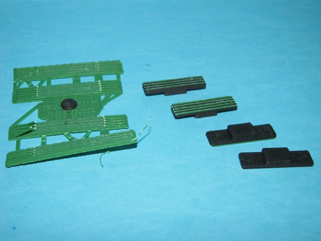
Two sets of keepers were fabricated as shown above on the raft with almost no support material.
The keepers were easily removed.
The bottoms of the keepers had green ABS support material residue as shown on the bottoms above. The tops were clear.
The bottoms were cleaned up using the Dremel sanding wheel. Two are clean, two still have residue in the photo above. Note the small holes that mark where the 0-82 screws will pass through. Although the holes were designed to clear, a clearance drill will be required to compensate for the tendency of the printer to close up holes slightly.
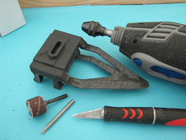
Clean up of the pilot truck frame was initially done using the Dremel sanding wheel and small round cutter bit and followed up with the model knife.
The bottom of the pilot is shown above after clean up.
The last step is hand tapping of the 0-82 screw threads into the bearing mount frames. The soft ABS plastic taps very readily by hand.
The photo above shows the trial fit of the keepers on the ends of the bearing frame posts.
Above is a bottom view of the pilot truck assembly with the wheels, axle and keepers in place.
The top photo above shows the assembled pilot truck.
finally, the pilot truck is attached to the pivot using a 3-48 screw and washers. The pivot frame between two locomotive side frames just forward of the front drivers is tapped to accept the bolt. The pilot wheels are centered in the upward jog of the front locomotive frame. The front frame is still not glued in place in the photo above. It requires some modifications to the front platform to make it square. The drop down section of the frame between the pilot wheels and front driver will mount the cylinder assembly after it is built. Also, the pilot equalization bar pivot will be located between the frame members where the cylinders mount.


No comments:
Post a Comment