Friday, November 23, 2012

Expansion Link and Brackets

Revised:  11/23/12          Subject to Revisions


The expansion link brackets and their mounts had been designed in the earliest stages of learning the Alibre Pro 3D CAD program more than a year ago.  Now that the cylinder assembly has been installed it is time to address the brackets and the expansion link itself.  On the model the links are about 2" long and pivot between two horizontal supports.  The expansion link brackets are in turn mounted between two fairly wide horizontal frames that mount to the frame and extend out beyond the drivers and drive rods.    The forward support also mounts the rear of the crosshead guides.    The front support is quite complex, thin and fairly large being some 5" wide and nearly 4" high and only a little of 1/8" thick.  This part would be a challenge to build on the 3D printer.

Crosshead Guide and Expansion Link Bracket Front Support As Printed

The author revised the design to fabricate the crosshead guide and expansion link bracket support in three parts that would later be glued together to form the overall part.  The above photo shows the three part sub-assembly as printed.  The top of the part as printed is actually the back side of the part.  The bar shown in the middle will join the two ends at left and right.

Crosshead Guide and Expansion Link Bracket Support Parts Before Cleaning

The above photo shows the support material residue on the right hand section which is removed on the left and joining bar at left and top in the photo above.   Two angle brackets with angled shoes will mount the overall assembly to the locomotive frame eventually.  The author realized that since this and the rear support must join several parts with some accuracy, drilling holes in the frame will await fit checking and fabrication of several other parts that mount on the support.  Parts that mount on the support frames will be attached with small 00-90 screws rather than glue so that that portion of the locomotive that support the valve and crosshead can be adjusted as needed.  The curved sections are boiler supports.  This is a busy part that must support many things: crosshead guides that must align with the cylinder piston and main connecting rod, expansion link which must align with the piston valve via the radius bar and fly crank through the fly-crank rod.

Rear Expansion Bracket Support rail as printed

The rear support for the expansion link support brackets is mounted across the frame and is nearly the same width as the crosshead guide support shown above.  This support also supports the boiler along the curved sections that protrude above the bar. 

Set of Frame Mounted Supports

The above set of frame mounted supports each provide support for various portions of the boiler as well as other parts of the locomotive mechanisms.  The top support is between the front and intermediate driver, the second is between the intermediate driver and main driver and finally the lower is between the main driver and rear driver.  Each mounts to the frame  with brackets that lie along the top of the frame and support the boiler above on the curved section.  The top and middle supports provide attachment for the expansion link brackets between them while the top support attaches the rear of the crosshead guides.

Expansion Link Bracket Set as Printed

The expansion link is a curved cam lever that is supported about 1/3rd of the way back of the first support frame.  It pivots to provide proper drive to a rod that in turn moves the piston valve.  The pivot is the hole in each bracket.  The expansion link is supported by two pivots, one on either side which are formed as a hole in the brackets that lie on each side of the link.

Expansion Link Brackets After Clean-Up

Like all printed parts the expansion link brackets have green ABS support material residue that is removed using the Dremel tool and model knife.  The large hole is the expansion link pivot.  Not readily seen are four smaller holes, two on each end that will be tapped for 00-90 mounting screws.

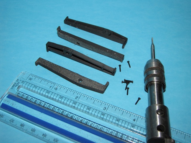
Expansion Brackets Being Tapped for 00-90 Screws

The four small pilot holes were hand tapped for the 00-90 screws as shown in the above photo.

Expansion Link Fit Checked in Brackets

The expansion link is a cam shaped to drive the radius rod that connects eventually to the piston valve.  The radius rod passes through the middle of the expansion link and rides in the curved slots on either side. 

Assembly of Inside Expansion Link Brackets to Front and Rear Supports

Top View of Expansion Link Inner Brackets, Front and Rear Support Assembly

The expansion link inner brackets were then assembled with the front and rear supports as shown above.  The brackets are held using small 00-90 screws.  They are so small they are nearly invisible in the photo. 

Closer View of Expansion Link Bracket Attached to Rear Support With 00-90 Screws

Fireman Side Expansion Link Installed in Brackets


The fireman side expansion link was installed between the bracket pair as shown in the above photo.  The link rotates freely around the white pivot that extends through the brackets.  The parts are held together with screws so that it can be progressively assembled on the locomotive and disassembled later if needed.

Expansion Link Bracket and Supports Fit Checked on Locomotive

The above photo shows the expansion link bracket and support assembly placed in position on the locomotive frame.  The expansion link is well outside the path of the rods and does not interfere.  An extension below the bracket on the front support will eventually support the crosshead guides.  So far this portion looks to fit well. 

White Side Rods

Revised:  11/23/12          Subject to Revisions


Pictures of various steam engines including Mikados often have what appear to be white or bright metal rods including side, main and valve rods.  Many also feature white sidewalls near the rims of drivers, pilot, trailing and tender truck wheels.  The author elected to replicate the black side rods in white for now.  They may be painted a silver light grey at a later time.  The same build files were used and the 2nd extruder material changed from black to white ABS.

White Intermediate Side Rods As Printed


Rear Side Rods as Printed

White Side Rods on Locomotive Model

The new white side rods work essentially identical to the black ones installed previously.  They needed the same amount of clean-up and fit they same.  The photo above also shows a white expansion link mounted on the link bracket.  The author intends to make all the side rods and cross slide rails in white to emulate those seen in the photos. 

Monday, November 12, 2012

Cylinder Block Covers

Revised:  11/12/2012          Subject to Revisions


Front Covers

Covers on front and back of the cylinder and valve bores complete the cylinder block assembly.  The first covers built were the front covers.  These do not have an opening for a rod.  Photographs of front covers on various Mikado locomotives indicate that they are plain.  More than likely the photographs depict insulated or isolated covers as no bolts are observed. 


Cylinder and Valve Front Cover Sets
Front covers are plain with the exception of a protrusion in the center.  In photographs protrusions on the larger cylinder covers appears to like a hockey puck in shape.  The covers also have rounded outer edges.  The valve covers have a short rod like protrusion.  These features were estimated based on photographs as the author did not have those features shown on USRA plan views. 

Inside and Outside of Front Covers
The outside of the covers do not have any remaining support material.  The inside was down on the raft and had support material that needed removal before installation. 

Inside View of Front Covers and Outside of Covers Placed on Cylinder Block

The Dremel sanding wheel was used to remove the bulk of the residual support material.  Very little touch-up was needed otherwise.  Some sanding of the interior of the cylinder block was done to provide a suitable fit for the front covers.

Front Covers Installed on Cylinder Block

The front covers were then glued in place on the cylinder block.  Super glue was used as was done for all prior gluing operations. 

View of Front of Cylinder Block with Covers

The front covers look very close to those seen in photographs of prototype locomotives.

Rear Covers

Isometric CAD View of Rear Valve Cover Design 
 
Drawings and photographs of the rear valve covers were converted to CAD design as shown above.  The rear valve cover has a modified bell-like housing to support the valve slide mechanism a short distance from the valve cover.  The author elected to simplify the housing a bit and eliminate the use of the slide which would be too small for an effective working model.  Instead a guide hole is provided to support the valve rod at the linkage end with dummy supports to surround the linkages.

Rear Valve Covers After Removal From 3D Printer

Printing went well with the rear valve covers.  Even the relatively small dummy bolts turned out fairly well.  The support material was used mainly to support the upper portion of the bell housing. 

Rear Valve Covers After Removal of Support Material

Support material was removed fairly easily with a needle nose pliers and model knife.  The valve rod holes were drilled out to make them clean for the eventual free movement of the valve rod.

Rear Covers Installed on Cylinder Block

The photos above and below show the rear valve covers installed on the cylinder block.  The valve rod will be operable (but not the valve) to illustrate the motion of the valve and linkage mechanisms on the model.

Close-up View of Rear Valve Cover

The rear valve cover is fairly small and is readily built on the 3D printer.  A small complex part such as this illustrates well the advantage of a 3D printer to make complex models.


CAD Isometric of Rear Cylinder Cover

The rear cylinder cover illustrated above will have two threaded blocks to attach the front of the cross slides to the cover.  The cross slides support the front slider of the main drive rod to prevent bending or distortion of the cylinder rod.  The rear of the slides are held on a support attached to the frame.

Rear Cylinder Covers As Removed From Printer

The rear cylinder covers have more details than those on the front.  The rear has a ring of dummy bolts plus the attachment blocks for the slides and of course the cylinder rod hole.   The printing came out very well with good detail.

Outside and Inside View of Rear Cylinder Covers

As for the rear valve covers support material inside the cover was removed to enable installation on the end of the cylinders.  This was done with the sanding wheel. 

Rear Cylinder Covers During Fit Check on Cylinder Block

Some grinding of the inside of the cylinders was done to facilitate a fit of the covers.  The region around the cylinder rod hole was cleaned out using a model knife.  After installation the rod hole will be drilled to final diameter.

Tapping Slide Mounting Blocks For 0-80 Screws

The pilot holes built into the slide mounting blocks were hand trapped for 0-80 screws.

Rear Cylinder Covers Installed on Cylinder Block


Rear Cylinder Covers With 0-80 Screws Inserted

View of Cylinder Block With Rear Covers in Place

The installation of front and rear covers essentially completes the cylinder block assembly.