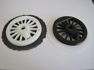
 After printing the factory test pattern (a small duck model) a locomotive driver wheel was printed using the same set-up, ie, white ABS for the raft and fill and black PLA for the model. The 3D CAD model is fairly complicated with 421 faces, 1025 edges and 603 vertices. The model is 2.66 inches maximum diameter and 0.52 inches thick.
The 3D model printed on the BFB-3000 was good with the exception of the flange. The flange is quite thin and located on the lowest layers. Apparently subsequent printing of the tire portion of the wheel injected sufficient heat to distort the flange.
The wheel and factory duck model are shown with a ruler for size. The duck model is quite smooth as is the wheel. The duck had a couple of very small imperfections under the chin of the duck. As was mentioned the wheel flange is badly distorted. The white layer under the wheel is the raft of white ABS plastic. It is composed of alternating X and Y grids to provide a level surface and good attachment interface between the build table of the machine and the model.
Another Axon file was created defining the same wheel model be built in reversed materials. The raft will be black PLA while the model will be white ABS. both models are shown at left. This time the flange came out good. The density of internal fill was reduced for the white version which resulted in a few internal voids, one can be seen on the right side. Future ABS runs will call for a higher fill density or alternate fill pattern to reduce or eliminate the voids.
Measurements made of the wheel indicated some error of dimensions. To study the error possibilities a line and space test pattern was prepared using the Alibre 3D CAD software to evaluate lines and spaces from 0.100 inches down to 0.01 inches. The design is shown at left. Each line and space combination was printed twice in both the X and Y axis forming two "L"s of lines with the target dimension width and space. The next lower size is spaced the same amount giving two spaces for evaluation. The dimensions are 0.1", 0.08", 0.06", 0.05", 0.04", 0.03", 0.025", 0.020", 0.015", 0.01" and 0.008". The printer information indicates that vertical walls such as used in the model must be at least 0.025" thick, so the lower dimensions are expected to have problems.
The resulting print with an ABS raft and using PLA material for the model is shown at left. The print appears quite good for the three larger lines of 0.1, 0.08, and 0.06 inches. The next lines at 0.05", 0.04", 0.03", 0.025" and finally 0.02". The Axon software eliminated the smaller dimensional lines of the 3D model. All lines are the same 0.25" height. Overall the model looks very good, but did exhibit various dimensional errors.
The blue line on the graph at left shows the ideal dimensions for the lines measured while the red dots show the actual value averages for four measurements at various positions on the lines. The dotted line is a curve fit showing the trend of the red dots. It is evident that as the line width increases the dimension develops an error of up to 0.012" or so while the smaller lines approach correct dimensions.
The graph at left depicts the space measurements vs the correct values. Once again there are errors which are most noticeable for middle size spaces around 0.05". Spaces at smaller dimensions are somewhat better while at the largest spaces the size is actually less that the design dimension. These errors are all for relatively small dimensions of 0.1" and below.
A large test grid design was prepared to evaluate the errors for very large dimensions up to 9". The pattern consists of squares of 1" X 1" with internal squares of 0.5" X 0.5" with some of those having internal squares of 0.25" X 0.25". The Axon software was again used with ABS raft and PLA model material.
The large grid pattern is shown at left with a ruler used to check for dimension accuracy. The spacing between inch marks on the ruler exactly matched the position of the 1" X 1" grid bars in both dimensions. Also, the 0.5" X 0.5" bars were similarly accurate in spacing. Once again the bar widths exhibited errors similar to those observed with the line and space test pattern. This pattern is near the largest X and Y dimensions for the printer and provides a good check of large part fidelity.


The BFB-3000 reveals a new field of creativeness. This 3D printer has recently been up-to-date by using a touch screen and renamed the 3DTouch. Using its open and clear design and style, the 3DTouch is fantastic for the classroom, home or office atmosphere. Take your 3D CAD sketches to life, your only limit will be your personal imagination!
ReplyDelete3D CAD Program